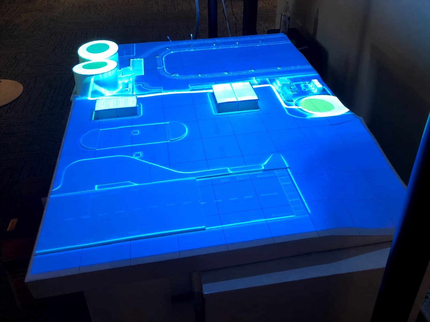
H2.0 Smart Water Network
A physical water-network simulation that made connected infrastructure tangible.
Project story
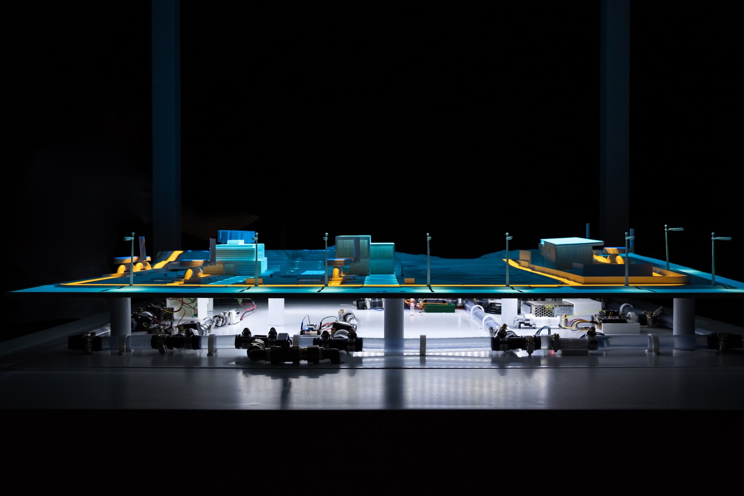
H2.0 turned a connected water network into something people could see, touch and follow. I focused on the physical installation: its structure, stand and construction logic.
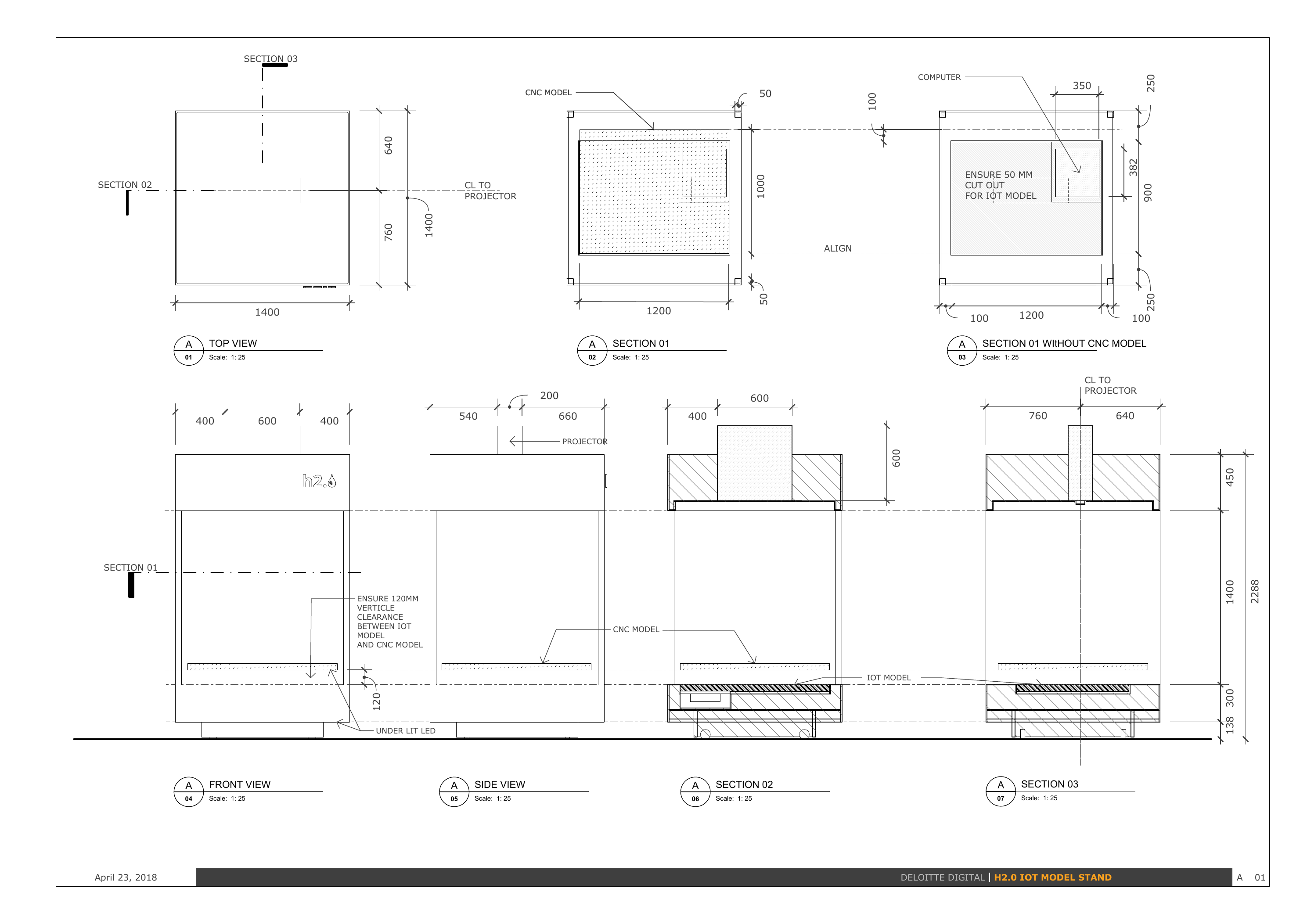
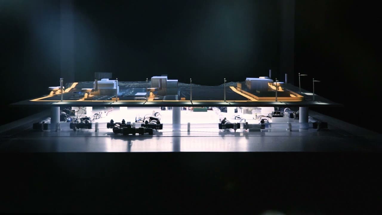
Drawing on my Interior Architecture roots, I treated the installation as a small piece of architecture. Technical drawings resolved the CNC-cut model and stand around water flow, connected components, projection sightlines and access for tuning.
Resolving the object
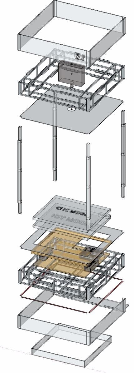
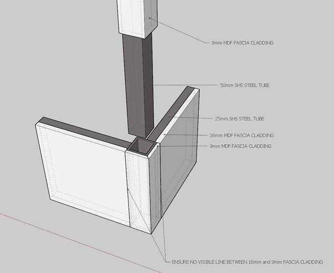
The main effort was resolving the structure and stand. Sections, elevations and exploded views coordinated the CNC-cut model, layered surfaces, component access and projection alignment before fabrication.
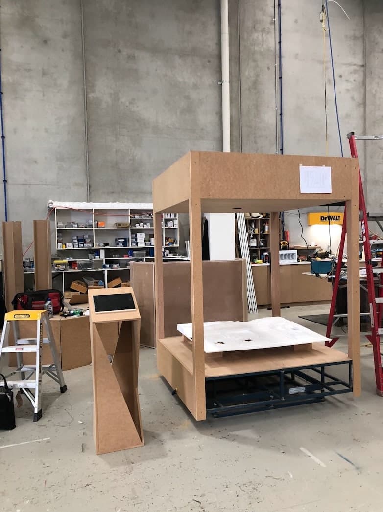
Building in layers
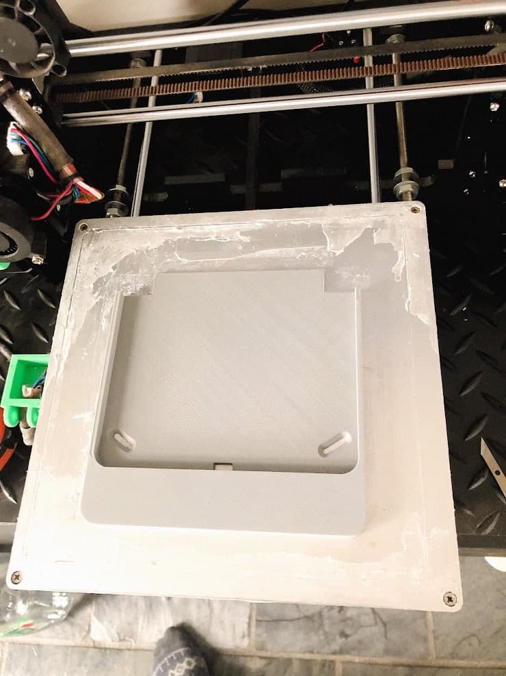
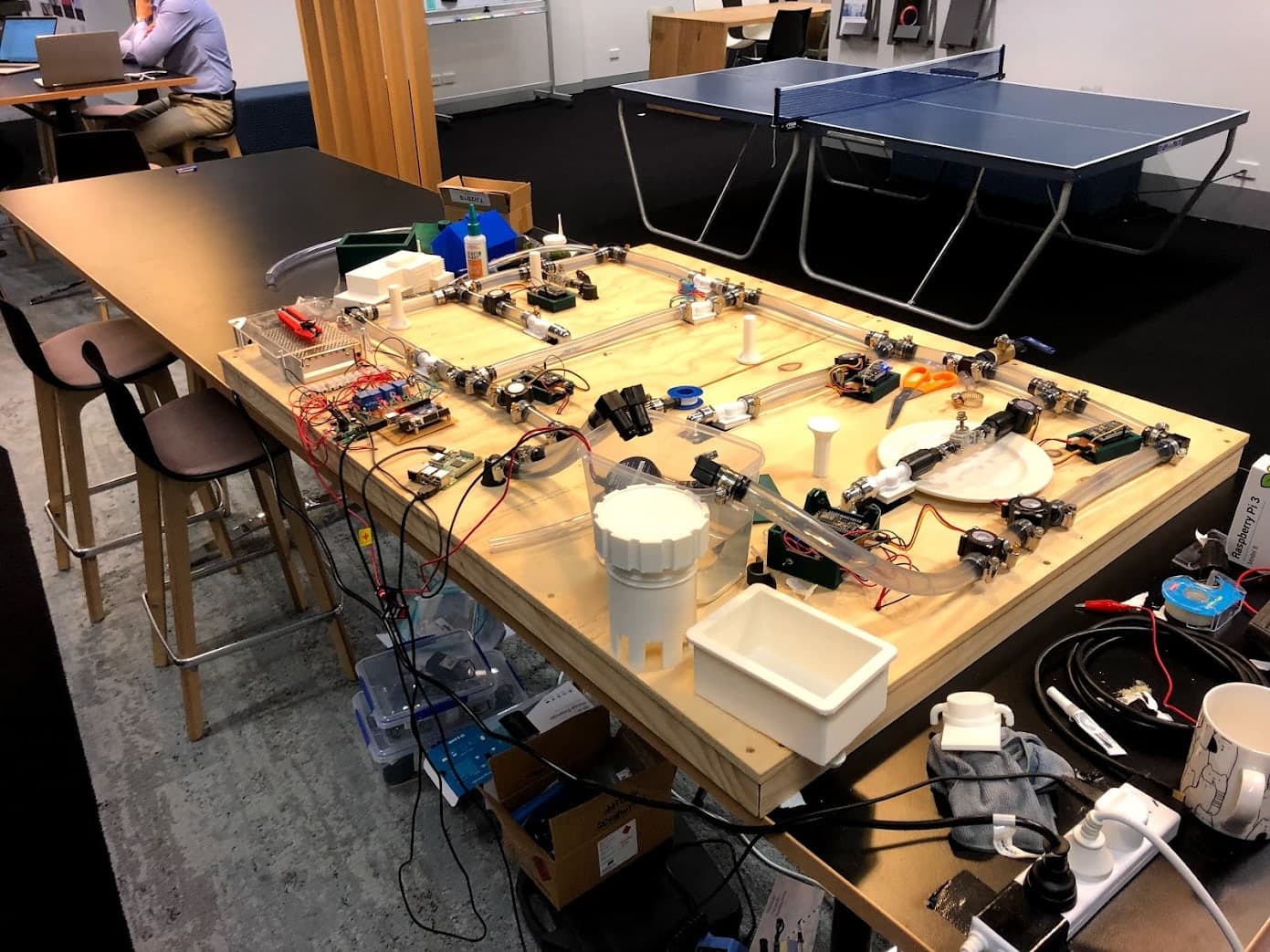
The model itself was CNC-cut. We 3D-printed selected housings, light fittings and scenery pieces, then kept tweaking the fit as water and projection were tested. Failed prints and leaks made weak points visible early.
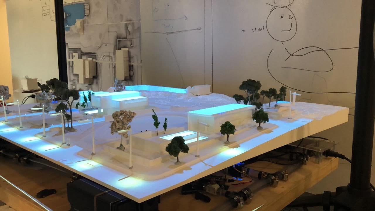
Bringing the network to life
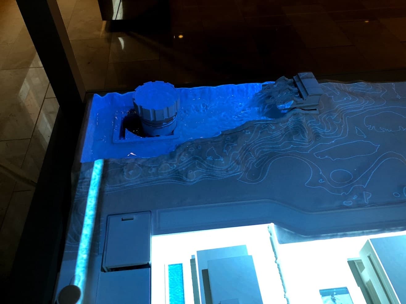
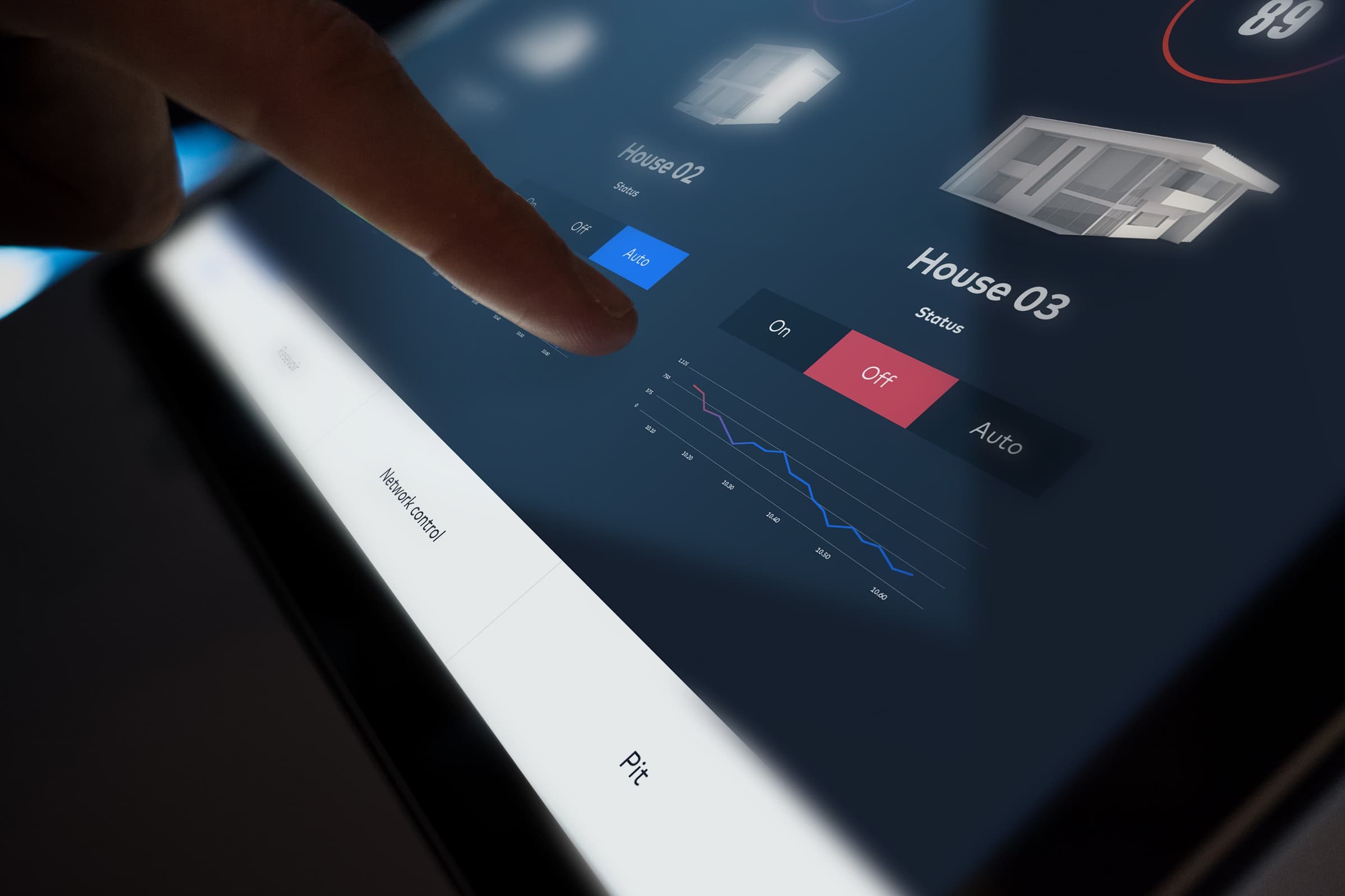
Working with IoT specialists on the connected system and motion specialists on the projection, I helped coordinate how their work fitted the physical model. Touch controls changed the scenario; projection made its effect legible across the network.
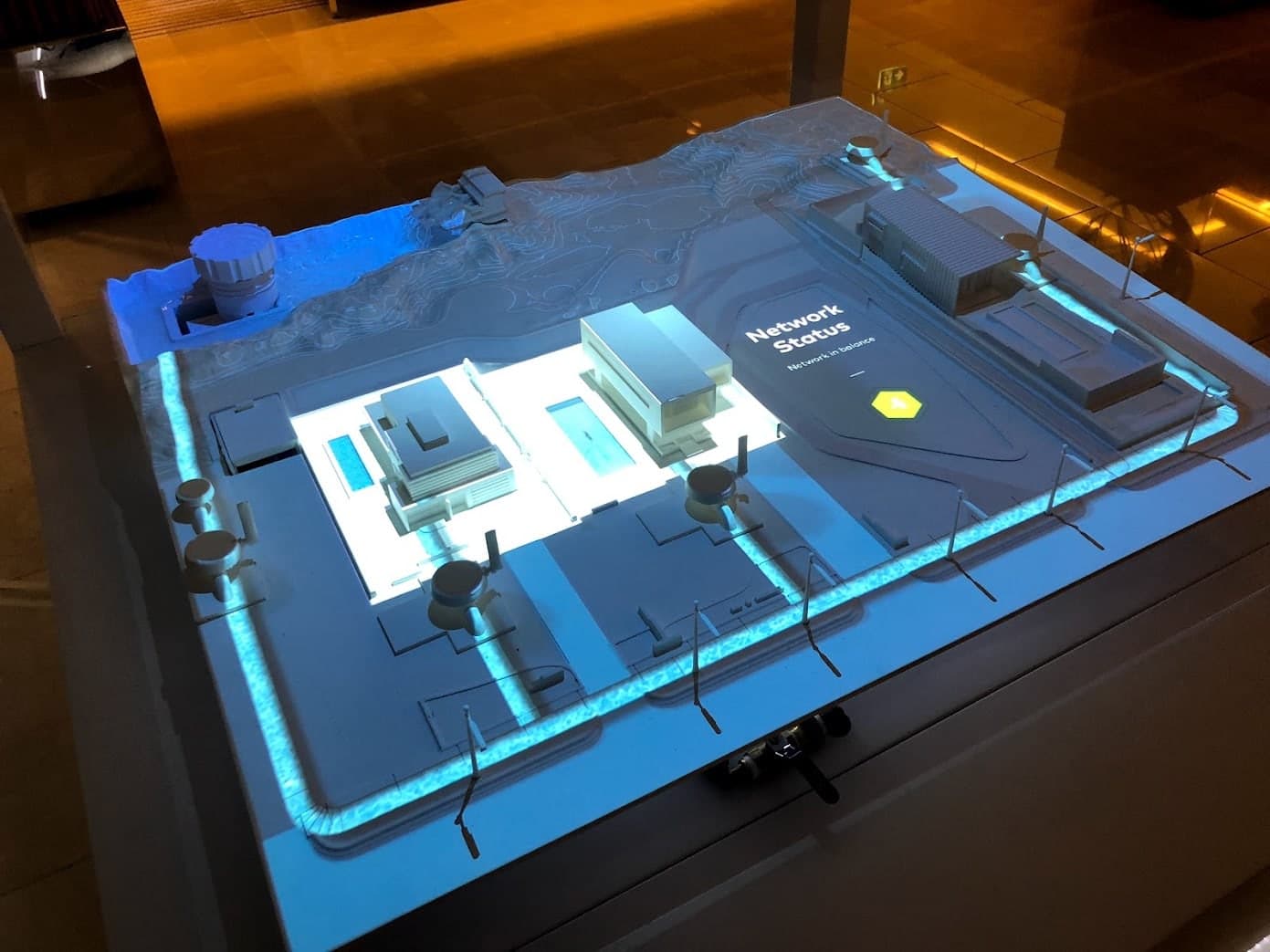
H2.0 was shown on Deloitte's Innovation Floor in Melbourne, where the physical simulation could be experienced directly.
Where it led
The interest around H2.0 led to a later confidential fuel-management prototype. I took on more of the physical model and build, carrying the same approach into a practical operational scenario.